
How to solve the problem of electricity and communication with a single cable ?
—— OPPC fiber optic cable selection
Table of Contents
Toggle- Energy + communication in one cable !
High Voltage Theft Protection - Key support for smart grids
- More safety against lightning and ice storms
Product description
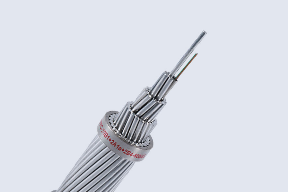
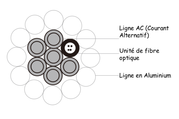
The OPPC cable (Fiber Optic Composite Aerial Phase Conductor) is an innovative optical cable that integrates electrical power transmission and optical fiber communication. By incorporating fiber optic units inside the phase conductor, it ensures both energy transmission and high-speed communication. It is mainly used in distribution networks medium and high voltage 10 kV to 110 kV (such as urban and rural networks) and is particularly suitable for lines without guard cable. OPPC cable can replace one of the traditional three phase conductors, thus avoiding the additional installation of communication infrastructure. Its main advantages lie in its energy efficiency (line design optimization), on theft protection (live operation), on resistance to lightning and frost impacts (no risk of lightning on a ground cable) and its high reliability (mechanical and electrical performance adapted to phase conductors).
Construction
| Driver | Aluminum strands, aluminum alloy or aluminum-steel, ensuring both electrical conduction and mechanical support. |
| Optical fiber unit | Stainless steel or aluminum tube containing single-mode/multi-mode optical fibers (typical number of fibers : 24-48). |
| Isolation | Cross-linked polyethylene (XLPE) or weather-resistant polyethylene, with a nominal voltage of 10 has 220 kV. |
| Outer sheath | Polyethylene (PE) anti-UV or flame-retardant polyolefin, suitable for harsh outdoor environments. |
Standard
According to IEEE 1138 and the IEC 60794-4
Properties
| Setting | Typical value / Beach |
| Section transversale | 50 – 420 mm² |
| Outer diameter | 12 – 35 mm |
| Electric resistance in direct current | 0,25 – 0,06 Ω/km (at 20 ° C) |
| Tension nominale | 10 – 220 kV |
| Short circuit current | 10 – 40 the (1 second) |
| Operating temperature range | -40° C at 90 ° C |
| Optical weakening | ≤0,22 dB/km (1310/1550 nm) |
| Tensile strength | 70 – 150 kN |
| Minimum bend radius | 20 × cable diameter |
Technical data
Structure parameters
| Model | Structure parameters | ||||||||
| Centre | First layer | Optical unit in stainless steel tube | |||||||
| Number of drivers | Nominal diameter mm | Material | Number of drivers | Nominal diameter mm | Material | Number of drivers | Nominal diameter mm | Maximum number of optical fibers | |
| OPPC-16B1-85/25 | 1 | 2.3 | 20AS | 5 | 2.3 | 20AS | 1 | 2.3 | 16B1 |
| OPPC-16B1-90/25 | 1 | 2.4 | 20AS | 5 | 2.4 | 20AS | 1 | 2.4 | 20B1 |
| OPPC-16B1-95/25 | 1 | 3.25 | 14AS | 5 | 3.25 | 20AS | 1 | 3.25 | 48B1 |
| OPPC-16B1-110/25 | 1 | 2.35 | 20AS | 5 | 2.35 | 20AS | 1 | 2.35 | 16B1 |
| OPPC-16B1-120/25 | 1 | 2.4 | 20AS | 5 | 2.4 | 20AS | 1 | 2.4 | 20B1 |
| OPPC-16B1-150/25 | 1 | 2.35 | 20AS | 5 | 2.35 | 20AS | 1 | 2.35 | 16B1 |
| OPPC-16B1-150/30 | 1 | 2.55 | 14AS | 5 | 2.55 | 14AS | 1 | 2.55 | 24B1 |
| OPPC-16B1-185/25 | 1 | 2.35 | 20AS | 5 | 2.35 | 20AS | 1 | 2.35 | 16B1 |
| OPPC-16B1-185/40 | 1 | 2.85 | 14AS | 5 | 2.85 | 14AS | 1 | 2.85 | 30B1 |
| OPPC-16B1-210/25 | 1 | 2.3 | 20AS | 5 | 2.3 | 20AS | 1 | 2.3 | 16B1 |
| OPPC-16B1-210/30 | 1 | 2.55 | 14AS | 5 | 2.55 | 14AS | 1 | 2.55 | 24B1 |
| OPPC-16B1-240/30 | 1 | 2.45 | 20AS | 5 | 2.45 | 20AS | 1 | 2.45 | 20B1 |
| OPPC-16B1-240/50 | 1 | 3.25 | 14AS | 5 | 3.25 | 14AS | 1 | 3.25 | 48B1 |
| OPPC-20B1+4A1a-400/35 | 1 | 2.5 | 14AS | 15 | 2.5 | SUSLG14 | 1 | 2.5 | 20B1+A1a |
| Model | Structure parameters | Nominal diameter mm | |||||
| Second layer | Third layer | ||||||
| Number of drivers | Nominal diameter mm | Material | Number of drivers | Nominal diameter mm | Material | ||
| OPPC-16B1-85/25 | 9 | 2.45 | AL | / | / | / | 13.8 |
| OPPC-16B1-90/25 | 9 | 3.6 | AL | / | / | / | 14.4 |
| OPPC-16B1-95/25 | 12 | 3.2 | AL | / | / | / | 16.5 |
| OPPC-16B1-110/25 | 8 | 4.2 | AL | / | / | / | 15.45 |
| OPPC-16B1-120/25 | 8 | 4.35 | AL | / | / | / | 15.9 |
| OPPC-16B1-150/25 | 11 | 2.6 | AL | 17 | 2.6 | AL | 17.45 |
| OPPC-16B1-150/30 | 12 | 2.55 | AL | 18 | 2.55 | AL | 17.85 |
| OPPC-16B1-185/25 | 10 | 3 | AL | 16 | 3 | AL | 19.05 |
| OPPC-16B1-185/40 | 12 | 2.8 | AL | 18 | 2.8 | AL | 19.75 |
| OPPC-16B1-210/25 | 9 | 3.35 | AL | 15 | 3.35 | AL | 20.3 |
| OPPC-16B1-210/30 | 10 | 3.22 | AL | 16 | 3.22 | AL | 20.53 |
| OPPC-16B1-240/30 | 9 | 3.6 | AL | 15 | 3.6 | AL | 21.75 |
| OPPC-16B1-240/50 | 12 | 3.2 | AL | 18 | 3.2 | AL | 22.56 |
| OPPC-20B1+4A1a-400/35 | 10 | 3.22 | HAL | 22 | 3.22 | HAL | 26.82 |
Other settings
| Model | Section transversale | Mass per unit length kg/km | Rated breaking load kN | DC resistance at 20 ℃ Ω/km | Reference current carrying capacity | Driver | ||||
| Aluminum clad steel wire mm² | Aluminum alloy wire mm² | Total mm² | ||||||||
| 40-70 ℃ | 40-80 ℃ | 40-90 ℃ | ||||||||
| OPPC-16B1-85/25 | 84.13 | 24.93 | 109.1 | 410 | 42.2 | 0.3106 | 251 | 307 | 352 | LGJ-95/15 |
| OPPC-16B1-90/25 | 91.61 | 27.14 | 118.8 | 446 | 45.9 | 0.2852 | 265 | 233 | 371 | LGJ-95/20 |
| OPPC-16B1-95/25 | 96.51 | 49.77 | 146.3 | 645 | 83.3 | 0.2665 | 281 | 345 | 397 | LGJ-95/55 |
| OPPC-16B1-110/25 | 110.84 | 26.02 | 136.9 | 491 | 47.3 | 0.2101 | 293 | 359 | 415 | LGJ-120/20 |
| OPPC-16B1-120/25 | 118.89 | 27.14 | 146 | 521 | 49.9 | 0.2242 | 305 | 374 | 430 | LGJ-120/25 |
| OPPC-16B1-150/25 | 148.66 | 26.02 | 174.7 | 597 | 54.1 | 0.1831 | 344 | 423 | 487 | LGJ-150/25 |
| OPPC-16B1-150/30 | 153.21 | 30.64 | 183.9 | 659 | 67.3 | 0.1799 | 349 | 430 | 195 | LGJ-150/35 |
| OPPC-16B1-185/25 | 183.78 | 26.02 | 209.8 | 693 | 58.7 | 0.1496 | 387 | 478 | 552 | LGJ-185/45 |
| OPPC-16B1-185/40 | 184.73 | 38.28 | 223 | 803 | 82.2 | 0.1489 | 391 | 484 | 560 | LGJ-210/25 |
| OPPC-16B1-210/25 | 211.54 | 24.93 | 236.5 | 762 | 63.9 | 0.1309 | 415 | 515 | 595 | LGJ-210/25 |
| OPPC-16B1-210/30 | 211.73 | 30.64 | 242.4 | 819 | 74.3 | 0.1317 | 419 | 519 | 601 | LGJ-210/35 |
| OPPC-16B1-240/30 | 244.29 | 28.29 | 272.6 | 875 | 73.1 | 0.1135 | 456 | 567 | 657 | LGJ-240/30 |
| OPPC-16B1-240/50 | 241.27 | 49.77 | 291 | 1045 | 104.2 | 0.1141 | 459 | 571 | 663 | LGJ-240/55 |
| OPPC-20B1+4A1a-400/35 | 29.45 | 390.88 | 420.3 | 1321 | 103.9 | 0.0725 | 620 | 760 | 869 | LGJ-400/35 |
OPPC vs ADSS vs OPGW
| Features | OPPC | ADSS | OPGW |
| Position d’installation | Replaces a traditional phase conductor, works under voltage | Suspended independently in the non-conductive area of the tower | Replaces the guard cable, positioned at the top for lightning protection |
| Conductivity | High (carries the working current) | None (fully dielectric structure) | High (short circuit current path) |
| Mechanical resistance | Very high (must withstand the voltage of the phase conductor) | Average (reinforced with aramid fibers) | Very high (must withstand the tension of the guard cable) |
| Electromagnetic interference | Sensitive to corona effects and magnetic fields | Strong resistance to interference | Exposure to lightning strikes and electromagnetic inductions |
| Applications | New transmission lines or replacement of phase conductors | Adding communication to existing lines | Replacement of the guard cable on high/ultra high voltage lines |
| Typical cost | Pupil (similar to OPGW) | Bas | Pupil |
ZMS OPPC Cable Applications
Theoretically, OPPC cable can be used on lines of different voltages. In some regions, OPGW is already widely adopted as a shield cable for communication on power networks of 110 kV to 1000 kV. However, OPPC is favored on lines where installing OPGW or ADSS is difficult :
- The lines of 10 kV, 35 kV and certain lines of 66 kV do not have a shield cable or only partially, making OPGW installation impossible.
- Some old lines of 110 kV pose challenges in data collection and tower load calculation, making the modification of pylon heads complex or costly.
- Constraints such as insufficient ground clearance, difficulties in managing crossings, the low resistance of the pylons and the frequent changes of route limit the use of the ADSS cable.
- Using a standard optical cable exposes you to the risk of theft and high maintenance costs, while communications with operators are sensitive to weather conditions and terrain.
Line design principles
- The OPPC cable carries permanent direct current in a three-phase network, which requires taking into account the impact of high temperatures on the transmission of optical fibers and their lifespan, as well as the thermal stability of the system.
- The OPPC must have mechanical and electrical characteristics similar to those of the other two phase conductors : diameter, weight, section, resistance and impedance.
- The ohmic resistance and impedance of the OPPC cable must be close to those of the other phase conductors in order to maintain three-phase balance and avoid any voltage fluctuation at the end of the line.
- Since the OPPC cable is live, specific insulation accessories as well as dedicated connection boxes are necessary for intermediate connections and electrical substation entries.
- To guarantee the safety of the installation, the quality of the project and facilitate maintenance interventions, it is recommended to limit the length of a reel of OPPC cable to 3 km maximum.
Advantages of ZMS OPPC cables
Economy
- When using OPPC cable on new lines : The construction and design of the line are carried out in a single step, which improves efficiency and reduces project costs. Requirements for tower height and strength can be reduced appropriately.
- When renewing existing lines with OPPC cable : There is no need to change existing line conditions. Only one phase needs to be replaced, and the performance of the OPPC remains consistent with that of the existing phase line. If the pylons are safe and reliable, a thorough recalculation or significant inspection is not required when replacing an OPGW with an OPPC.
Lower risk of breakage due to lightning
- Unlike OPGW overhead cable, the OPPC functions like a normal phase line, without increasing the risk of rupture linked to lightning.
- OPGW provides grounding and communication on high voltage lines, but lightning can seriously disrupt these functions, thus threatening the stability of the electricity network.
Better resistance to icing
- Currently, there is no effective solution for de-icing OPGW fiber optic cables on power lines.
On the other hand, the OPPC cable, thanks to its higher operating temperature, Significantly improves the line's resistance to icing.
Security against theft
- OPPC cable junction boxes are powered by the electrical network and installed on high voltage insulators. Their position, much higher than that of OPGW and ADSS cables, significantly reduces the risk of theft.