

- All Posts
- News
- Blog
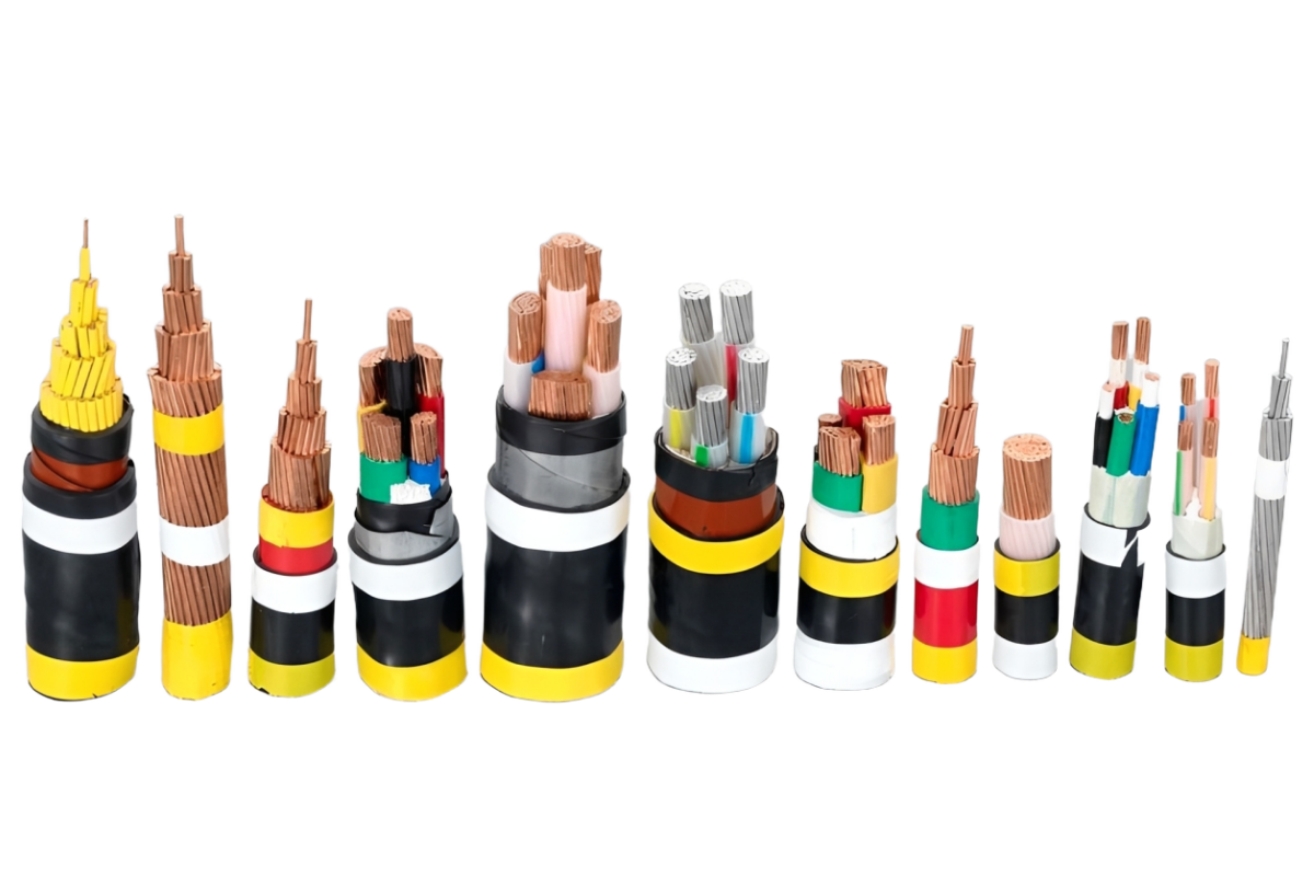
- Electric cable types
January 13, 2026/
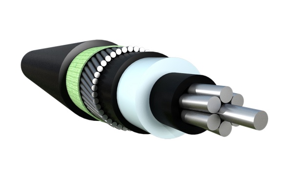
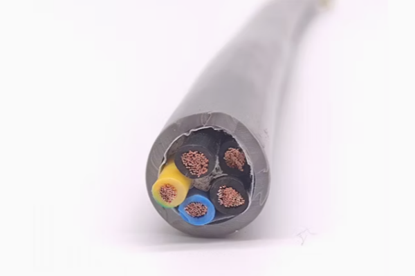
XLPE insulated low voltage cable, halogen-free, with concentric screen. Complies with IEC standards 60502-1, IEC/EN 60332-3-24, IEC/EN 60754-1/2...
September 23, 2025/
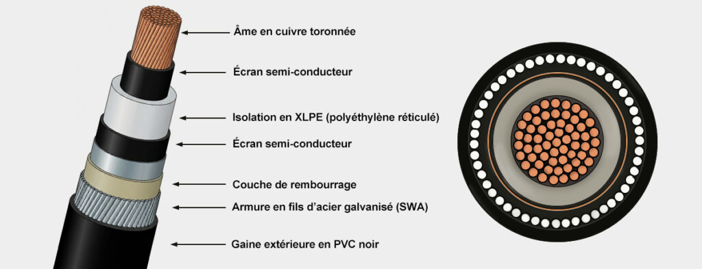
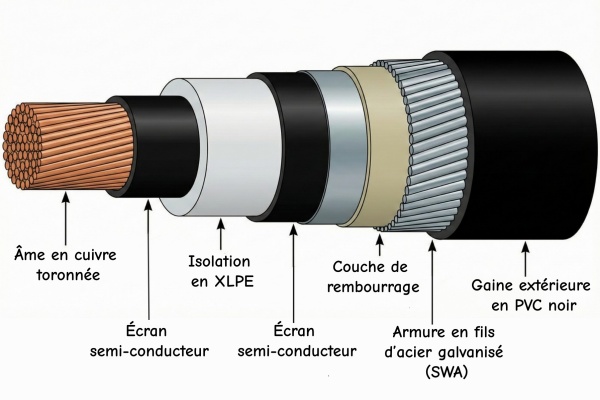
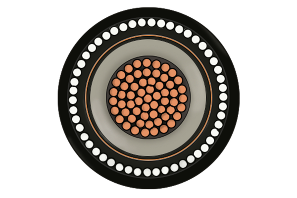
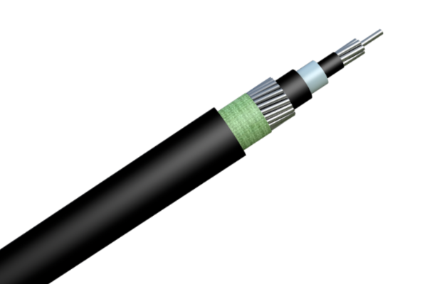
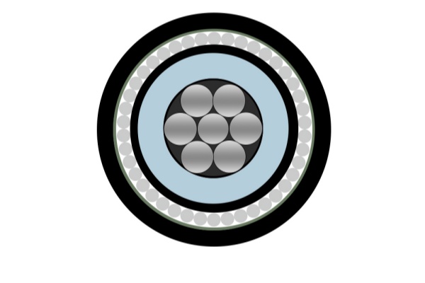
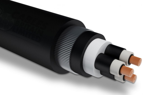
The N2XSY cable is a medium voltage cable (MV) with XLPE insulation and PVC sheath, designed for distribution...
- All Posts
- News
- Blog
- Electric cable types
July 25, 2025/
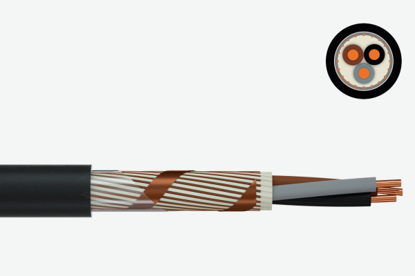
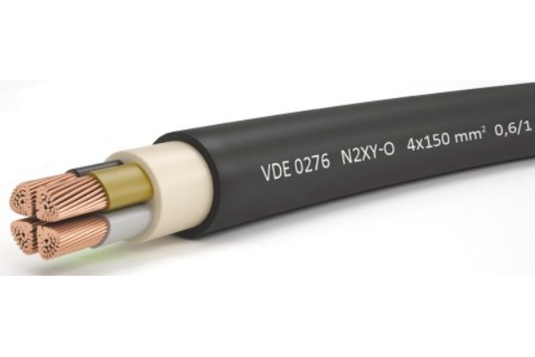
N2XY cable Low voltage power cable 0,6/1 kV, ideal for fixed industrial and tertiary installations Copper conductor...