N2XS2Y cables are single-core XLPE insulated copper conductor medium voltage cables with a polyethylene outer jacket (PE). Their composition is in many respects similar to their N2XSY equivalent, whose outer sheath is PVC. Nevertheless, the high endurance of PE gives the N2XS2Y variant significantly greater resistance to mechanical stress during installation and operation. We also offer N2XS cables(F)2Y and N2XS(FL)2Y, which feature water-repellent tapes for increased water resistance.
Construction
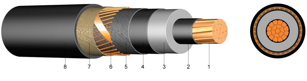
1. Bare copper wire with stranded conductors (RM) 2. Inner layer of semiconductor material 3. Cross-linked polyethylene core insulation 4. Outer layer of semiconductor material 5. Bulking band 6. Copper wire screen 7. Sealing strip 8. Polyethylene outdoor sheath (PE) (Custom cable services to meet all your needs)
Application
N2XS2Y cable is a medium voltage power cable, designed to be placed directly in the ground, in the water, outdoors, indoors and in wiring conduits. It offers excellent electrical performance and great mechanical protection, and is widely used for power transmission and distribution.
Standard
HD620 10C, IEC 60502-2, IN 60228 Class 2 From vde 0276-620, HD 620 S1 : 1995, YOUR ONE 60228 class 2 (construction)
Technical data
N2XS(F)2Y
Test voltage
6 / 10 kV
21 / 5 min.
12 / 20 kV
42 / 5 min.
18 / 30 kV
63 / 5 min.
Temperature range
Moving
from -20℃ to +90℃
Fixe
from -20℃ to +90℃
Operating temperature
Court-circuit
250℃
Short circuit time
Maximal [sec]
5
Radius of curvature
Minimal
15 times the diameter
Number of conductors and nominal section in mm²(6/10 kv)
Kg/km cover
Overall diameter approx. a etc
Diameter global max. approx value. a etc
Poids approx. and kg/km
Shore current carrying capacity in A
Air current carrying capacity in A
1×35 RM/16
518,40
23
28
820
187
197
1×50 RM/16
662,40
24
29
960
220
236
1×70 RM/16
854,40
26
31
1.200
268
294
1×95 RM/16
1.094,4
27
32
1.450
320
358
1 x 120 RM/16
1.334,4
29
34
1.700
363
413
1 x 150 RM/25
1.723,2
30
35
2.000
405
468
1 x 185 RM/25
2.059,2
32
37
2.350
456
535
1 x 240 RM/25
2.587,2
34
39
2.900
526
631
1 x 300 RM/25
3.163,2
36
41
3.550
591
722
1 x 400 RM/35
4.233,6
40
45
4.500
662
827
1 x 500 RM/35
5.193,6
43
48
5.550
744
949
Number of conductors and nominal section in mm²(12/20 kv)
Kg/km cover
Overall diameter approx. a etc
Diameter global max. approx value. a etc
Poids approx. and kg/km
Shore current carrying capacity in A
Air current carrying capacity in A
1 x 50 RM/16
662,40
28
33
1.150
222
239
1 x 70 RM/16
854,40
30
35
1.350
271
297
1 x 95 RM/16
1.094,4
31
36
1.600
232
361
1 x 120 RM/16
1.334,4
33
38
1.850
367
416
1 x 150 RM/25
1.723,2
34
39
2.250
409
470
1 x 185 RM/25
2.059,2
36
41
2.600
461
538
1 x 240 RM/25
2.587,2
39
44
3.150
532
634
1 x 300 RM/25
3.163,2
41
46
3.800
599
724
1 x 400 RM/35
4.233,6
44
49
4.750
671
829
1 x 500 RM/35
5.193,6
47
52
6.450
750
927
Number of conductors and nominal section in mm²(18/30 kv)
Kg/km cover
Overall diameter approx. a etc
Diameter global max. approx value. a etc
Poids approx. and kg/km
Shore current carrying capacity in A
Air current carrying capacity in A
1 x 50 RM/16
662,40
33
38
1.350
225
241
1 x 95 RM/16
1.094,4
36
41
1.900
327
363
1 x 120 RM/16
1.334,4
38
43
2.200
370
418
1 x 150 RM/25
1.723,2
39
44
2.550
414
472
1 x 185 RM/25
2.059,2
41
46
2.950
466
539
1 x 240 RM/25
2.587,2
43
48
3.500
539
635
1 x 300 RM/25
3.163,2
46
51
4.150
606
725
1 x 400 RM/25
4.233,6
49
54
5.050
680
831
1 x 500 RM/35
5.193,6
52
57
6.200
765
953
Comparison between N2XS2Y, N2XS(F)2Y and N2XS(FL)2Y
/
N2XS2Y XLPE PE – 6/10 (12) kV
N2XS cable(F)2Y XLPE – 6/10 (12) kV
N2XS cable(FL)2Y XLPE – 6/10 (12) kV
Driver
Stranded copper (Class 2)
Semiconductor layers
Semiconductor material
Isolation
XLPE (Cross-linked polyethylene)
External semiconductor layer
Semiconductor material
Screen
Copper wires
Copper wires and copper tape
Ribbon
/
Inflatable band in water
Ribbon 2
/
Strip of aluminum foil tightly tied to the sheath
Outer sheath
PE (Polyethylene)
Benefits
1. Excellent electrical performance : High purity copper conductor, high conduction efficiency, high temperature resistant XLPE insulation, suitable for medium and high voltages (6kV to 36kV). 2. Double shielded structure : Metal shielding and outer sheath shielding to effectively prevent electromagnetic interference, suitable for environments requiring high quality electrical energy. 3. Great environmental resistance : Corrosion resistant outer sheath, to humidity and UV, ideal for humid or harsh environments ; compression resistant, tensile and mechanical damage. 4. High transmission capacity : XLPE insulation increases current carrying capacity and reduces line losses. 5. Installation flexible : Good flexibility, suitable for complex terrain or confined spaces. 6. Long life and low maintenance : Resistant to aging, high stability, lifespan of up to 35 ans, thereby reducing operating and maintenance costs.